| Transmission | Uni- | bidirectional |
|---|---|
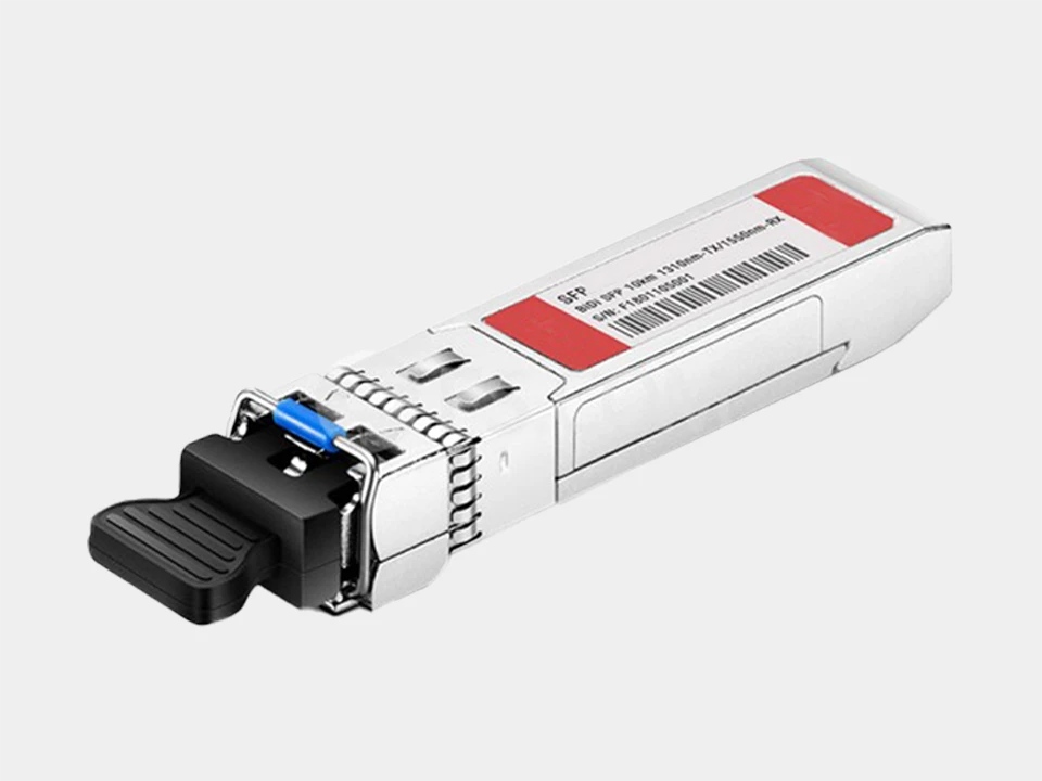
| Fibre optic connection | LC |
| Fibre type | Multimode | Singlemode |
| Optical range | ≤ 80 km (dep. on SFP module) |
| Digital signals (24V DC) | 4...256 |
| Analogue signals (V | mA) | 0...16 |
| Precision (analogue signals) | ± 0.2 % |
| Signal delay (latency) | ca. 1.5...6.5 ms |
| Error monitoring | LED, relay, outputs |
| Power supply | 10...28 V DC |
| Dimensions (W x H x D) | 22.5 x 100 x 127 mm |
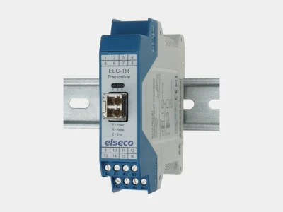
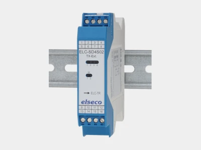
With the I/O-system ELC-TR, up to 256 signals (e.g. switching, control, clock, synchronous, fault signals or analogue measured values) can be transmitted unidirectionally or bidirectionally. The basic device is the ELC-TR-F-ME22-SFP transceiver, which can be equipped with various SFP modules for different fibre optic types (singlemode or multimode).
Two transceivers are required for each system. These can be extended with various additional modules depending on the required number of signals and their type (analogue or digital). The signals are transmitted over fibre optic cables (FO), which means that the fibre optic I/O-system ELC-TR ensures interference-free and fast data transmission in harsh industrial environments and in the field.
The absolute potential separation means that problems that can occur due to potential carry-over, interference voltages, etc. are fundamentally avoided. No software is required, nor are extensive settings or synchronisation necessary.
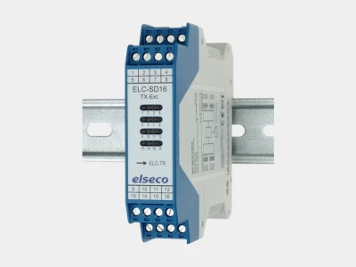
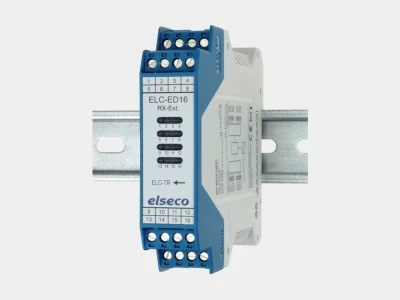
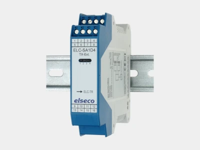
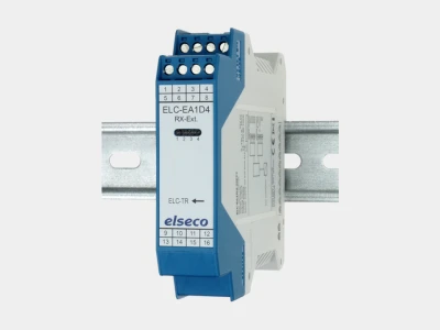
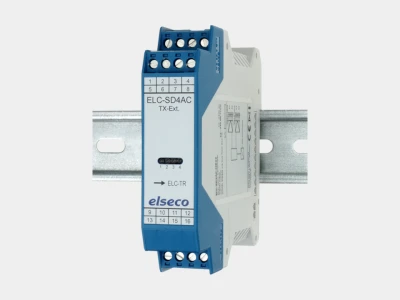
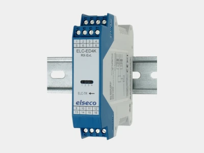
Extension devices
The basic device ELC-TR-F-ME22-SFP with fibre optic connection serves as a fibre optic converter to which the input and/or output modules are connected using the integrated pluggable device bus. The input signals are recorded and transmitted 1:1 to the remote station.
It is only necessary to ensure that the corresponding I/O expansion modules are plugged in the correct order on the transmitter and receiver side. Each I/O module occupies 16 bits of the 256-bit data package in the transmission protocol. With the I/O-modules ELC-SA1D4 and ELC-EA1D4 for analogue standard signals in particular, 12 bits (= resolution) are used for the analogue signal, which means that the 4 remaining bits can be used as 4 digital I/O signals.
The basic device also monitors the reception of the valid transmission protocol and contains a relay contact, which can be used as a fault signalling contact in addition to the visual signalling by the red LED. In the event of a fault, the NO contact opens (intrinsically safe even in the event of a power failure).

© elseco GmbH 2026