


| Transmission | unidirectional |
|---|---|
| Fibre optic connection | F-ST | F-SMA |
| Fibre type | Multimode | POF |
| Optical budget (typ.) | 9...15 dB |
| Optical range | 0.1...40 km |
| Digital signals (24V DC) | 8 | 16 | 24 | 32 |
| Signal delay (latency) | ca. 5 ms |
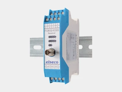
| Error monitoring | LED, relay, outputs (opt.) |
| Power supply | 12 V DC | 24 V DC |
| Dimensions (W x H x D) | 22.5 x 100 x 127 mm |
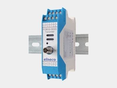
The fibre optic I/O system FOB32 transmits switching and control signals via fibre optic cables. Up to 32 digital switching signals (24 V DC) can be transmitted unidirectionally via fibre optic cables in a point-to-point connection. The I/O system FOB32 ensures interference-free and fast data transmission in harsh industrial environments or in the field. Absolute potential separation fundamentally prevents problems that can arise due to potential carryover, interference voltages, etc. The I/O system components are available with various fibre optic connectors (F-ST, F-SMA) and different fibre types: multimode (G50/125μm, G62.5/125μm), POF (990/1000μm).
With up to 3 expansion devices (slaves), the basic device can be expanded by 8 inputs or outputs each to a maximum of 32 inputs or outputs. To do this, the expansion devices are simply connected to the basic device via the side housing bus. No software is required, and no settings or adjustments are necessary. Installation and commissioning are therefore extremely simple.
The digital signals are transmitted by the transmitter as a protocol via fibre optic cables to a receiver. The receiver converts the data and outputs it again as a switching signal. An LED on the front of the fibre optic I/O receiver signals faulty conditions (including fibre breakage, excessive attenuation, transmitter failure). A firmware variant is available as an option, which causes the receiver outputs to drop in the event of a fault.

© elseco GmbH 2026